Metrics IDE (Requires ICV)

Integrated Development Environment

ide_broch_thumb

Product Brochure

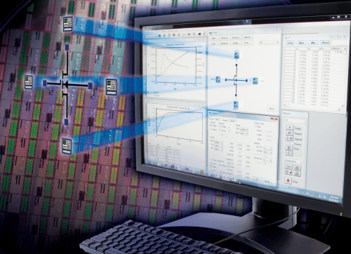
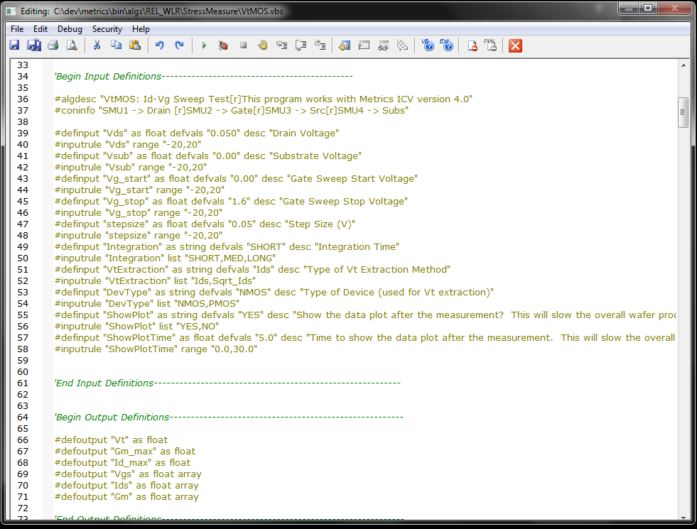
This add-on to ICV provides an integrated VBScript test development environment
including a comprehensive editor, debugger and execution engine. Several
libraries and functional APIs are included providing access to the ICV
communications server, instrument drivers, pulse generators, oscilloscope
drivers as well as thermal and prober driver templates. Math function libraries
are also included for performing parameter extraction and decision branching.
Use the IDE to modify the included WLR, NVM, and parametric algorithms or
develop your own.

Request a 30-day Trial
Request a Quote

New Features

Features / Enhancements
• Updated Metrics IDE algorithm suites and performed some code refactoring and optimization.
• General clean-up of VBScript Algorithms including issues with parameter caching.
• Resized the wafer map display size in the “Wafer Map Editor” to support larger wafers with small die.
• General clean-up of the IDE algorithms and refinement of plotting routines for these algorithms; HCI, NBTI, NBTI-OTF.
• Optimized Charge Pumping and added correction for tunneling current to existing VBScript code.

Probe Driver Improvements
• Added VBScript drivers in Metrics IDE for Micromanipulator P300L with vision support.
• Corrected probe control chuck separation/contact state management to avoid marking wafers during probe plan verification.
• Updated NucleusVision.svbs driver to add additional error reporting and logging capability.

Other Improvements / Additions
• Added ‘directio.ini’ file to ‘C:\Metrics\instintdrvs’ directory in installation. NOTE: Adding this file and directory to installer file required creating a Service Pack release. Appying this update will overwrite all existing installation files so a full backup of modified files in the \algs directory is recommended before applying this update.

IDE Algorithm Suites


Capacitance vs. Voltage

Algorithm NameDescriptionNotes
CVCalibrationCalibration functions for the 4980, 4284, 4285, and B1500
CVFrequencySweepA sweep of the oscillator bias while measuring device parameters
CVBiasSweepA sweep of the DC bias while measuring device parameters
CVBiasSweep_with_HysteresisA sweep of the DC bias while measuring device parameters with a return sweep to the starting bias
CVTimeSweepMeasurement of device parameters as a function of time
CVSinglePointA single point measurement of device parameters
CVMinimumPhaseAngleA sweep of the Impedance and Phase Angle to extract Capacitance. The sweep occurs at several DC bias points
CV2FrequencyMeasurementA measurement of Impedance and Phase Angle at two frequencies to extract Capacitance. The measurements occur at several DC bias points

Wafer Level Reliability - Oxides

Algorithm NameDescriptionNotes
J_RAMPA current ramp test that increases the applied current to the Gate while measuring the charge (Qacc) and voltage. The device is ramped at a constant time interval until breakdown or the maximum current is appliedstop criteria PercentChangeV
outputs Vbd, Qbd, Fail mode
V_RAMPA voltage ramp test the increases the applied voltage to the Gate while measuring the charge (Qacc) and current. The device is ramped at a specified rate until breakdown or the maximum voltage is appliedstop criteria Percent ChangeI
outputs Vbd, Qbd, Fail mode
J_RAMPBA current ramp test just like the J_RAMP test, except the device is ramped to a maximum current and then the current is held constant until breakdown or the maximum time is exceededstop criteria PercentChangeV
outputs Vbd, Qbd, Fail mode
calculates Slp (log slope I vs V)
V_TDDBA constant voltage is applied to the device while the resulting current is monitored for breakdown. Breakdown can be defined as exceeding a threshold value or changing by a certain percentagestop criteria PercentChangeI
outputs Tbd, Qbd, Fail mode
I_TDDBA constant current is applied to the device while the resulting voltage is monitored for breakdown. Breakdown can be defined as exceeding a threshold value or changing by a certain percentagestop criteria PercentChangeV
outputs Tbd, Qbd, Fail mode
V_SILCA constant accelerated stress voltage is applied to the device while the resulting current is monitored for breakdown. At specified intervals, the voltage is lowered to a use voltage and the resulting current is measured. Breakdown can be defined as exceeding a threshold value or changing by a certain percentagestop criteria PercentChangeI
outputs Tbd, Qbd, Fail mode

Wafer Level Reliability - Stress Measure

Algorithm NameDescriptionNotes
HCIA combined algorithm that performs all functions of a traditional HCI test. This algorithm allows for the specification of both the Vt and Single Point Tests as well as the stress conditions and times. The device is subjected to the stress-measure cycle until a device parameter exceeds specified conditions or the maximum stress time has occurredstop criteria IdMax, %DegVt, %DegGM
VtMOSThis test sweeps the Gate voltage while applying a constant Drain voltage and measuring the Drain current. This test can be combined with the Stress algorithms to create a testcalculates Vt from Id (linear), Id_sat (saturation)
IspotThis algorithm applies a bias to the Gate, Drain, and Substrate of the device while grounding the source. The resulting current values are measuredoutputs Ids, Igs, Isub
GummelThe Base-Emitter voltage is swept while the Collector voltage is held constant. The resulting Base and Collector currents are measured and the Gain is calculatedoutputs Bf, Bf_max, Vbe_on
RGummelThe Base-Collector voltage is swept while the Emitter voltage is held constant. The resulting Base and Emitter currents are measured and the Gain is calculatedoutputs Br, Br_max, Vbc_on
DCStressA constant accelerated stress voltage is applied to the device. The substrate current can be monitored to stop the device stressstop criteria max time exceeded or % change of any monitored current
supports 4-ch monitoring
ACStressA constant accelerated stress voltage is applied to the device. The AC signal is applied using a pulse generator. The substrate current can be monitored to stop the device stressstop criteria max time exceeded or % change of any monitored current
supports 4-ch monitoring
CP_CAA constant amplitude AC signal is placed upon the gate of the device while the substrate current is measured. The voltage offset is changed to move the carriers toward the oxide junctionoutputs Nit, Nit_corr, Isd, Itun, Icp_max, Nit_max
CP_VAA variable amplitude AC signal is placed upon the gate of the device while the substrate current is measoutputs Icp, Icp_corr, Isd, Itun, Icp_max
CP_VFA variable frequency AC signal is placed upon the gate of the device while the substrate current is measuredoutputs Icp, Icp_corr, Isd, Itun, Icp_max, Qss, Dit
NBTIA combined algorithm that performs all functions of a traditional NBTI test. This algorithm allows for the specification of the Vt test as well as the stress conditions and times. The device is subjected to the stress-measure cycle until a device parameter exceeds specified conditions or the maximum stress time has occurredstop criteria Vt_stop, %DegVt
outputs Id0, Id1..n, Vt, %DegVt
NBTI-OTFA combined algorithm that performs all functions of a traditional NBTI On-the-Fly test. The test alternates stress and measurement cycles. The method of the device sweep and stress is designed to minimize the amount of time the device is not being stressed. The test allows the user to select several different parameters to monitor and use for the stopping of a teststop criteria Id_stop, %DegId
outputs Id, %DegId, Fail mode

Non Volatile Memory - Capacitor(s) Reliability

Algorithm NameDescriptionNotes
NVMCycleCapApplies pulse cycles to an NVM capacitor
NVMPulseCapApplies pulses to an NVM capacitor
NVMRampCycleCapApplies ramped pulse cycles to an NVM capacitor
NVMRampPulseCapApplies ramp pulses to an NVM capacitor
NVMCycle2Cap*Applies pulse cycles to two (2) NVM capacitors simultaneously* requires dual channel PGU
NVMPulse2Cap*Applies pulses to two (2) NVM capacitors simultaneously
NVMRampCycle2Cap*Applies ramped pulse cycles to two (2) NVM capacitors simultaneously
NVMRampPulse2Cap*Applies ramp pulses to two (2) NVM capacitors simultaneously.

Non Volatile Memory - Device Reliability

Algorithm NameDescriptionNotes
NVMCycleDev*Applies pulse cycles to an NVM device gate terminal* requires supported SMU to bias for other device terminals
NVMPulseDev*Applies pulses to a NVM device gate terminal
NVMRampCycleDev*Applies ramped pulse cycles to a NVM device gate terminal
NVMRampPulseDev*Applies ramp pulses to a NVM device gate terminal

Instrument Support


Semiconductor Parameter Analyzers and DC Sources

VendorModelDescriptionNotes
HP (Agilent)4142BModular DC Source/Monitor
HP4145A/BSemiconductor Parameter Analyzer
HP (Agilent)4155A/B/CSemiconductor Parameter Analyzer
HP (Agilent)4156A/B/CSemiconductor Parameter Analyzer
AgilentE5270B8-slot Precision Measurement Mainframe
- E5280BHigh Power Source/Monitor Unit (HPSMU)
- E5281BMedium Power Source/Monitor Units (MPSMU)
- E5286AHigh Resolution Source/Monitor Unit (HRSMU)
- E5287AAtto Level High Resolution Source/Monitor Unit
- E5288AAtto Sense and Switch Unit
Agilent5272A2-slot High Speed Source Monitor Unit
Agilent5273A2-slot High Speed Source Monitor Unit
Agilent E5260A8-slot High Speed Measurement Mainframe
- E5290AHigh Power Source/Monitor Unit (HPSMU)
- E5291AMedium Power Source/Monitor Units (MPSMU)
Agilent5262A2-slot High Speed Source Monitor Unit
Agilent5263A2-slot High Speed Source Monitor Unit
KeysightB1500ASemiconductor Device Analyzer
- B1510AHigh Power Source/Monitor Unit (HPSMU)
- B1511AMedium Power Source/Monitor Units (MPSMU)
- B1514A50us Pulse Medium Current Source/Measure Unit (MCSMU)
- B1517AHigh Resolution Source/Monitor Unit (HRSMU)
- B1520AMulti-frequency Capacitance Measurement Unit
KeysightB1505APower Device Analyzer/Curve Tracer
- B1512AHigh Current Source/Monitor (HCSMU, DHCSMU)
- B1513AHigh Voltage Source/Monitor (HVSMU)
- B1514A50us Pulse Medium Current Source/Measure Unit (MCSMU)
- N1258AModule selector
KeysightB2900APrecision Source/Measure Unit
- B2901A100 fA Single Channel Precision Source/Measure Unit
- B2902A100 fA Dual Channel Precision Source/Measure Unit
- B2911A10 fA Single Channel Precision Source/Measure Unit
- B2912A10 fA Dual Channel Precision Source/Measure Unit
KeithleyModel 236*Source Measure Unit*When using more than one of these instruments together, you will need the 2361 TCU and all connectors
KeithleyModel 237*High Current Source Measure Unit
KeithleyModel 238*High Current Source Measure Unit
Keithley2400 Series*Digital Source Meter
- 2410*Digital High Voltage Source Meter
- 2420*Digital High Current Source Meter
- 2430*Digital High Power Source Meter
Keithley2600A SeriesDigital Source Meter
- 2601A20W Single Channel Source Meter
- 2602A20W Dual Channel Source Meter
- 2611A200V Single Channel Source Meter
- 2612A200V Dual Channel Source Meter
- 2635A1 fA 20W Single Channel Source Meter
- 2636A1 fA 20W Dual Channel Source Meter
KeithleyModel 90I-V Semiconductor Test System
Keithley4200-SCSSemiconductor Characterization System
QualiTauDSPT9012Desktop Semiconductor Parametric Tester

Capacitance and LCRZ Meters

VendorModelDescriptionNotes
HP (Agilent)4284A*Precision LCR Meter20 Hz-1 MHz (* supported in CV Algorithm Suite)
HP (Agilent)4285A*Precision LCR Meter75 Hz-30 MHz
HP (Agilent)4294A*Impedance Analyzer40 Hz-110 MHz
Keysight (Agilent)E4980A*Precision LCR Meter20 Hz-2 MHz
Keysight (Agilent) B1520A*Multi-frequency Capacitance Measurement Unit1 kHz - 5 MHz

Switch Matrix and Multiplexers

VendorModelDescriptionNotes
HP4084A/4085ASwitch Matrix Controller and Matrix48-Pin
Keysight (Agilent)E5250ALow-Leakage Switch Mainframe
- E5252ALow-Current Switch Matrix Card10 input x 12 output
- E5255AMultiplexer Card2 input x 24 output
Keysight (Agilent)B2200A14ch Low-Leakage Switch Mainframe
- B2210AfA Low-Leakage Switch Module14 input x 12 output
Keysight (Agilent)B2201A14ch Low-Leakage Switch Mainframe
- B2211ALow-Leakage Switch Module14 input x 12 output
KeithleyModel 706Scanner Mainframe
KeithleyModel 707Switch Matrix Mainframe
- Model 7071General Purpose Matrix Card8 input x 12 output
- Model 7072Semiconductor Matrix Card4 input x 12 output
- Model 7072-HVHigh Voltage Semiconductor Matrix Card8 input x 12 output
- Model 7073Coaxial Matrix Card
- Model 7074General Purpose Mux Card(8) 1 input x 12 output
- Model 70752-Pole General Purpose Mux Card(8) 1 input x 12 output
- Model 7076Dual 2-Pole Mux Card(2) 4 input x 12 output
- Model 7077Isolated Coaxial Matrix Card8 input x 12 output
KeithleyModel 707ASwitch Matrix Mainframe
- Model 7172Low Current Matrix Card8 input x 12 output
- Model 7174Low Current High-Speed Matrix Card8 input x 12 output
KeithleyModel 707B*Switch Matrix Mainframe* No SCPI support - must set to IDDC compatibility mode
KeithleyModel 708Single Slot Switch Mainframe
KeithleyModel 7001Switch Control Mainframe
KeithleyModel 7002Switch Control Mainframe
MRD4x28 MuxSwitch Matrix/Mux Module4 input x 28 output

Semi-Auto and Full-Auto Probers

All stations are controlled via GPIB. Metrics software should not reside on the probe PC due to resource conflicts.
VendorModelDescriptionNotes
CascadeSummit 10000Semi-automatic Probe Stationrequires Nucleus v.4.x or Velox 2.0 Software
CascadeSummit 12000Semi-automatic Probe Stationrequires Nucleus v.4.x or Velox 2.0 Software
CascadeS300Semi-automatic Probe Stationrequires Nucleus v.4.x or Velox 2.0 Software
CascadeElite-300Semi-automatic Probe Stationrequires Nucleus v.4.x or Velox 2.0 Software
CascadePS-21Automatic Probe Station
Alessi (Cascade)GalaxySemi-automatic Probe Stationrequires version 5.20H
Suss Microtech (Cascade)PA200Semi-automatic Probe Stationrequires Prober Bench Software v.7.x
Suss Microtech (Cascade)PA300Semi-automatic Probe Stationrequires Prober Bench Software v.7.x
Suss Microtech (Cascade)PS200Semi-automatic Probe Stationrequires Prober Bench Software v.7.x
Suss Microtech (Cascade)PS300Semi-automatic Probe Stationrequires Prober Bench Software v.7.x
Micromanipulator8860Semi-automatic Probe Stationrequires pcProbe 2.6 and pcBridge Software
Micromanipulator4460Semi-automatic Probe Stationrequires NetProbe Software
Micromanipulator9920Semi-automatic Probe Stationrequires NetProbe Software
Vector SemiconductorVX-3000SVSemi-automatic Probe Station
VX-3000SV Semi-automatic Probe Station
AX-2000Semi-automatic Probe Station
Lucas SignatoneSemi-automatic Probe Stationrequires Interlink Controller and GPIB control installed
TELP-8XLAutomatic Probe Station
TELP-12XLAutomatic Probe Station
TEL19SAutomatic Probe Station
TSKA-PM-90Automatic Probe Station
AccretechUF300Automatic Probe Station
AccretechUF2000Automatic Probe Station
AccretechUF3000Automatic Probe Station
Electroglas1034Automatic Probe Stationwith Option D, GPIB Control
Electroglas2001 SeriesAutomatic Probe Stationrequires GPIB Control
Electroglas3001 SeriesAutomatic Probe Stationrequires GPIB Control
Electroglas4085Automatic Probe Station
Electroglas4090Automatic Probe Station

Pulse Generator Units

VendorModelDescriptionNotes
HP (Agilent)8110APulse Generator150 MHz, +- 20V, 50 Ohm
HP (Agilent)81110APulse Pattern Generator165 MHz, +- 10V, 50 Ohm
330 MHz, +- 3.8V, 50 Ohm
HP (Agilent)41501A/B*Pulse Generator Units* for use with HP4155 or HP4156 Semiconductor Parameter Analyzer (supports 16440A SMU/PGU selector)

Thermal Controllers

VendorModelDescriptionNotes
CascadeAllThermal Chuckrequires Nucleus 4.x or Velox 2.0 Software
Suss Microtech (Cascade)AllThermal Chuckrequires Nucleus 4.x or Velox 2.0 Software
Micromanipulator8860Thermal Chuckrequires pcTC Software

Custom Instruments

VendorModelDescriptionNotes
4 DimensionsCV90MMercury Probe SystemRS-232 Control


System Requirements


* See System Requirements for ICV software product. ICV is required to use the Integrated Developer Environment (IDE).

Documentation


Integrated Development Environment (IDE)


IDE 4.4 Digital Download Guide


You may also like…